Pelton Turbine Test Rig
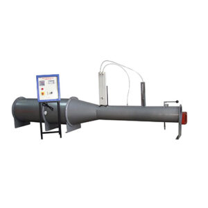
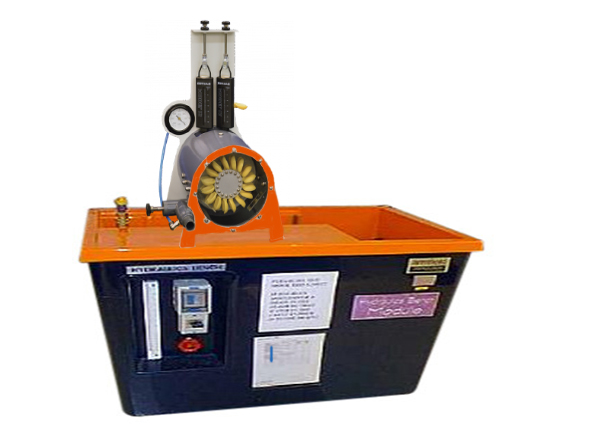
Experimental unit consists of the Pelton wheel, a needle nozzle used as distributor, a band brake for loading the turbine and a housing with a transparent front panel. The transparent cover enables to observe the water flow, the Pelton wheel and the nozzle during operation. The nozzle cross-section and thus the flow rate are modified by adjusting the nozzle needle.
The turbine torque is determined by force measurement on a band brake and is read on spring balances. For measuring the rotational speed, a non-contact speed sensor.
The water jet is accelerated in a nozzle and hits the Pelton wheel tangentially. In the blades on the circumference of the Pelton wheel the water jet is deflected by approximately 180°. The impulse of the water jet is transmitted to the Pelton wheel.
This accessory comprises a miniature Pelton wheel with spear-valve arrangement mounted on a support frame, which fits on to the Hydraulics Bench top channel. Mechanical output from the turbine is absorbed using a simple friction dynamometer.