Ammeter
Ammeter is an electronic instruments device used to determine the electric current flowing through a circuit. Ammeters measuring current in milli-ampere range is known as milli-ammeters. Common types of ammeters are moving-coil ammeter and moving-iron ammeter. Ammeters are connected in series to the circuit whose current is to be measured. Hence this electronic instruments are designed to have as minimum resistance/ loading as possible. It is used commonly in electronics lab.
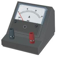
Ammeter- Electronic Instruments
Moving Coil Ammeter
Moving coil ammeters are used to measure DC Currents in electronics lab. This electronic instruments consists of a coil suspended by two hair springs. This coil is placed in a magnetic field created by a fixed permanent magnet. A torque is experienced when current passes through this coil which is proportional to the current. When the coil turns, the springs will exert a restoring force proportional to the angle turned. By these two forces, the coil will stop at some point and the angular deflection will be proportional to the current.
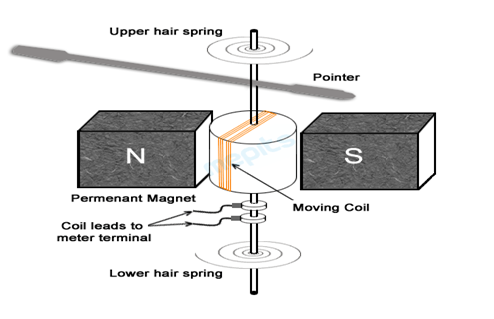
Moving coil ammeter – Electronic Instruments
Moving Iron Ammeter
Moving iron ammeters as electronic instruments can be used for measuring both direct and alternating currents in electronics lab. In this type of ammeter, a piece of soft iron is used. This iron piece constitutes of a moving vane and a fixed vane. Current to be checked flows through a fixed coil placed around the iron piece. This coil produces a magnetic field proportional to the current. So the iron pieces will get magnetized with the same polarity. The movable vane turns away from the fixed vane due to magnetic repulsion. As the iron turns, the spring of the electronic instruments will exert a restoring force and stop the vane, when both the forces become equal. The pointer of the ammeter is attached to the movable vane, which will point to the proper current reading using a calibrated scale.
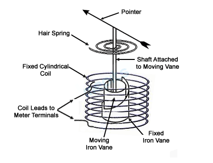
Moving Iron Ammeter – Electronic Instruments
Voltmeter
Voltmeter is an electronic instruments used in an electric circuit to determine the potential difference or voltage between two different points. Digital and analog voltmeters are available in electronics lab. They are usually connected in parallel (shunt) to the circuit. Hence they are designed to have maximum resistance as possible to reduce the loading effect. This device is also common in electronics lab.
Analog Voltmeter
Analog voltmeter is a type of voltmeter and electronic instruments with an extra connection of a series resistor (high resistance). It consists of a movable coil placed in a magnetic field. The coil ends are connected to the measuring terminals. As current flows across the coil, it will start turning due to magnetic force excreted on the coil and thus the hair spring will stop the coil by an equal and opposite restoring force. Angular rotation will be proportional to the voltage in this electronic instruments.
Digital Voltmeter

Digital voltmeters can measure both AC and DC measurements with high accuracy as an electronics instrument. It can measure a high voltage up to 1 kV. Main component of a digital voltmeter is an Analog to Digital Converter (ADC). Voltage to be measured is amplified or attenuated properly by the circuit and the output is sent to an Analog to Digital Converter (ADC) IC. This IC will convert the analog signal input to digital signal output. A digital display driven by this IC will display the proper voltage value.
Oscilloscope

Oscilloscope is an electronic instruments used to measure constantly varying signal voltages. This instrument will provide a graphical representation of the input signal on its screen and hence it is used in electronics lab. Cathode Ray oscilloscope is the main type of oscilloscope. It consists of a cathode ray tube and its associated circuits. Cathode ray tube is composed of an electron gun, horizontal and vertical deflection plates and a phosphorus screen. Input signal is vertically amplified by an amplifier and fed to a delay channel. The input signal is not directly applied to the vertical plates it is delayed for a period of time by the delay channel. If delay time is not used then a part of the signal gets lost. Voltage applied to deflection plate causes the electron beam from electron gun to fall on to the phosphorus screen and appear as a glowing dot moving on the screen. Negative voltage causes the dot to move downwards and positive voltage causes the dot to move upwards. Signals to the trigger circuit will trigger the time based generator and produce horizontal sweeps. Time based generator signal moves the glowing dot across the screen from left to right within a specific time interval. Due to the rapid sequence by many sweeps, the glowing dot will blend into a solid line. In each second the dot may sweep across the screen up to 4-5 lakh times. The combined effect of the vertical deflection and the horizontal sweeping, traces a graph of the input signal on the screen.
Digital Storage Oscilloscope (DSO)
Digital storage oscilloscope is a digital electronic instruments device used to measure, store and display the input signal. DSO will record the signal digitally into its memory and display it whenever needed.

DSO has 4 sections: vertical section, horizontal section, data acquisition section and display section. Vertical section takes the input signal from the selected range. Amplitude adjustments of the signal can be done in this section. From vertical section, the signal is fed to the acquisition section, in which the signal is sampled to digital values using an ADC. The sampling rate is according to the clock generated by the horizontal section. More than one sample points are stored in the memory as waveform points. All the waveform points together make a waveform record. The start and stop points of the record is determined by the trigger system. Display section will fetch the data from the memory to display it on the screen.

DSO – Electronic Instruments
The DSO is the digital version of conventional oscilloscope. The DSOs offer a wide range of analytical facilities. Contrary to the conventional system, the incoming signals are digitized using an ADC unit and the signals are processed using digital signal processors. In addition to the display functions, various mathematical operations such as addition, subtraction, multiplication etc can be performed in a DSO. The waveforms can be analyzed, memorized or processed using DSOs. DSOs can be used to analyze high frequency and high voltage signals which are often required in modern electronic research and studies.
Multimeter
Multimeter is an electronic instruments used to measure different electrical parameters such as voltage, current, resistance etc. It is the common electronic instruments used to troubleshoot the faults in all electrical and electronic devices. Digital multimeters are most commonly used in electronics lab since they offer better precision and accuracy and are cheaper compared to the analog versions. It will show the numerical values in its digital display.
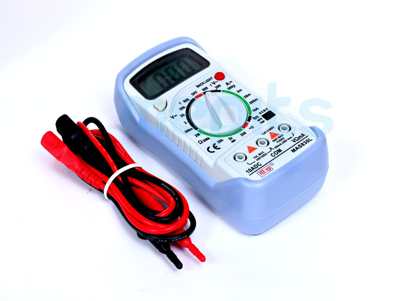
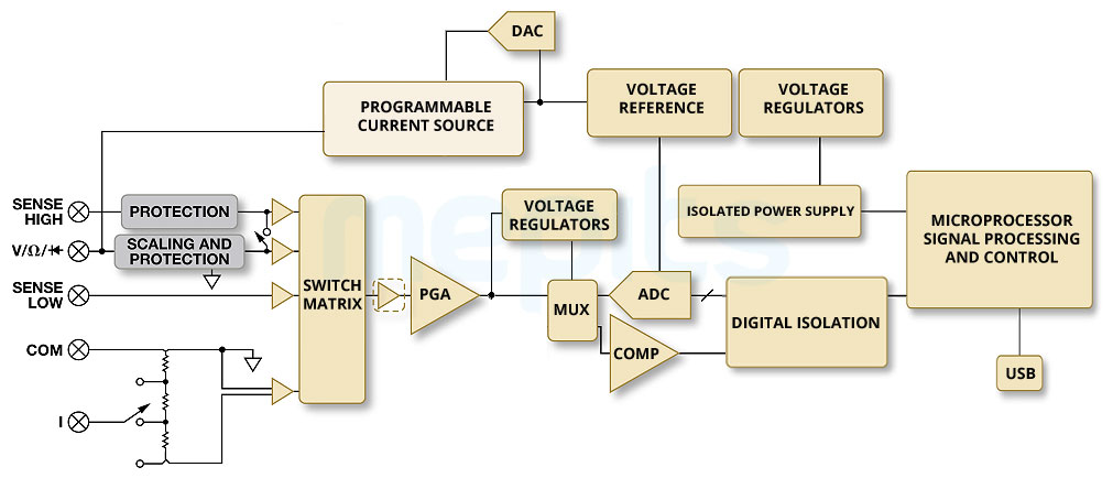
Multimeter – Electronic Instruments in Electronics Lab
To measure the value of a resistor, probes of the multimeter are connected across the resistor. The multimeter is switched to resistance measurement mode (position 1). Then current from the constant current source will flow through the resistor and a potential difference is created across the resistor. According to ohm’s law, this potential difference is proportional to its resistance. A buffer amplifier will amplify this voltage and feed it to an analog to digital converter (ADC). The digital display will show the value in ohms based on the output from the microprocessor.

For measuring AC current, the probes of the multimeter are connected in series to the circuit. The multimeter is switched to AC current measurement mode (position 2). In this case, it is to be ensured that the positive probe is connected to the current measurement plug on the multimeter. The current to be measured is converted into proportional voltage by current to voltage converter. AC voltage is rectified by a rectifier circuit. The rectifier output voltage is converted into proportional digital signal by Analog to Digital Converter (ADC). Then, Digital display will show the value in amperes.
For measuring AC voltage, connect the AC voltage across the probes. Switch the multimeter to AC measuring mode (position 3). The AC voltage passes through an attenuator which attenuates the signal, if it is above the selected range. The rectifier circuit will rectify AC voltage into DC. Analog to Digital Converter will produce a digital signal proportional to the DC voltage, to get the digital display in volts.
To measure DC current connect the current to multimeter probes. Switch multimeter to DC current measuring mode (position 4). Here also it is to be ensured that the positive probe is connected to the current measurement plug on the multimeter. By the use of a current to voltage converter, the input signal is converted into a proportional voltage. Using this voltage, analog to digital converter produces a digital signal to display the value in amperes.
If DC voltage is given as input, then we have to switch the multimeter to DC voltage measuring mode (position 5). If the input is above the selected range, then the attenuator will attenuate the signal. The voltage is then given as the input of an Analog to Digital Converter. It will generate a digital signal and display the value in volts.
Clamp on meter
Clamp on meter is an electronic instruments measuring device used to measure current flowing through a conductor. By this type of meter we can conveniently measure the current in a live wire without any interruption to the circuit. Using this meter, large currents can be measured without shutting off or interrupting the circuit.

AC clamp meter consists of a bar current transformer in its jaws. When this jaws are clamped on a conductor, that conductor will act as primary. Magnetic flux due to the alternating current in the conductor will cut the secondary of current transformer. A current to voltage converter will convert the current in the secondary of a current transformer to its proportional voltage. An Analog to digital converter will make the signal digital. The microcontroller used will drive the display unit to show the reading.

DC current is flowing through the conductor in a fixed polarity. So magnetic field around the conductor is fixed and will not change. Due to this, for measuring DC current some changes in the AC clamp meter is needed.

Hall Effect is the main principle behind the working of a DC clamp meter. It is the production of a potential difference across a material, when a magnetic field is applied in a direction perpendicular to that of the flow of current. In this meter a sensor known as hall element is used. The Hall element responds to the magnetic field due to direct current in the conductor by producing a voltage across the element. This voltage is proportional to the current. It is then amplified and converted to digital value. With the help of a microcontroller value of current is displayed.
LC Meter
LC meter is an electronic instruments measuring device used to measure inductance and capacitance, also mentioned as LCR meter. In this meter, the impedance of the object is measured and from its impedance values the inductance and capacitance is measured. An AC voltage is given to the device under test. The circuit measures the voltage across the device and the current flowing through the device. From the ratio of these values its impedance is calculated. Then resistance component and reactance component is determined from the impedance of this electronic instruments. Using these values capacitance can be calculated. A Digital Display is used to show the values.


Q meter
This electronic instruments is used commonly in electronics lab. It is used generally to measure the electric properties of the capacitors and coils. This process is done by measuring the Q value of the circuit.
The basic principle used is the resonant rise of the voltage across the capacitor in the circuit.
If XL=Xc and E=IR
Q= (XL/R) = (XC/R)
Some of the uses of the Q Meter as an electronic instruments in electronics lab are:
- Coefficient of coupling
- Measure inductance and capacitance
- Find bandwidth
- Measure Q of the coil.